CAPABILITIES / TECHNICAL OVERVIEW

Precision Manufacturing Capabilities

Explore machining processes, materials, secondary operations, and the information needed to define a suitable manufacturing route.

Send Your Drawings
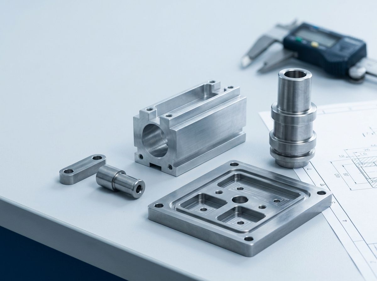
Representative precision components arranged with an engineering drawing
REPRESENTATIVE VISUAL

CAPABILITY MATRIX / 01

Process selection starts with the part requirements.

Use this matrix as an initial process-selection guide. Final manufacturing routes and resource availability are confirmed against each drawing and project requirement.

ProcessTypical features or scopeSuitable projectsReview focus
01

CNC Milling

Pockets, slots, hole patterns, complex profiles
Prototypes, custom components, repeat batches
Geometry, setup, datums, critical dimensions and inspection
02

CNC Turning

Shafts, sleeves, threads, flanges
Rotational components and repeat spares
Diameter, length, runout, threads and secondary operations
03

Precision Grinding

Qualified flat or cylindrical precision features
Applications requiring controlled geometry, dimension or finish
Material condition, hardness, stock allowance, geometry and inspection
04

Coordinated Secondary Processes

Finishing, treatment, deburring and assembly requirements
Completed-part and multi-process supply
Finish specification, masking, documentation and process compatibility

PROCESS DETAILS / 02

Manufacturing considerations by process.

Each manufacturing route is defined around the drawing, material, quantity, critical features, quality requirements, and intended application.
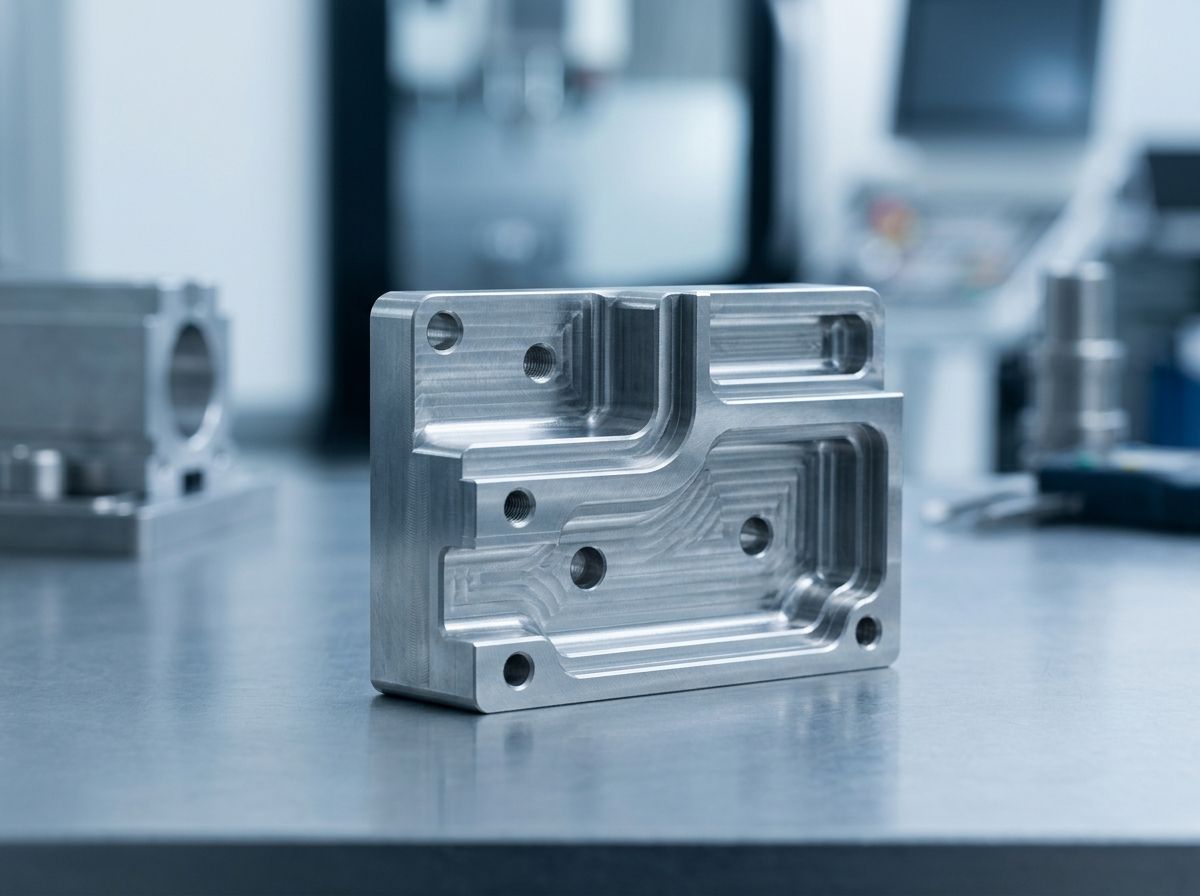
Representative visualization of a complex milled metal component
Representative manufacturing visual.
01

CNC Milling

Prismatic components, plates, housings and geometry requiring multiple controlled faces

Typical features

  • Pockets and cavities
  • Hole patterns
  • Threads and slots
  • Datum-controlled features
  • Multi-face machining requirements

Materials considered

Metals and engineering plastics, with specific grade and condition reviewed

Technical review focus

Setup strategy, datum structure, feature access, critical dimensions and inspection approach

What to provide

2D drawing, 3D model when available, material, quantity and identified critical features

PROCESS ROUTE / PROJECT SPECIFIC
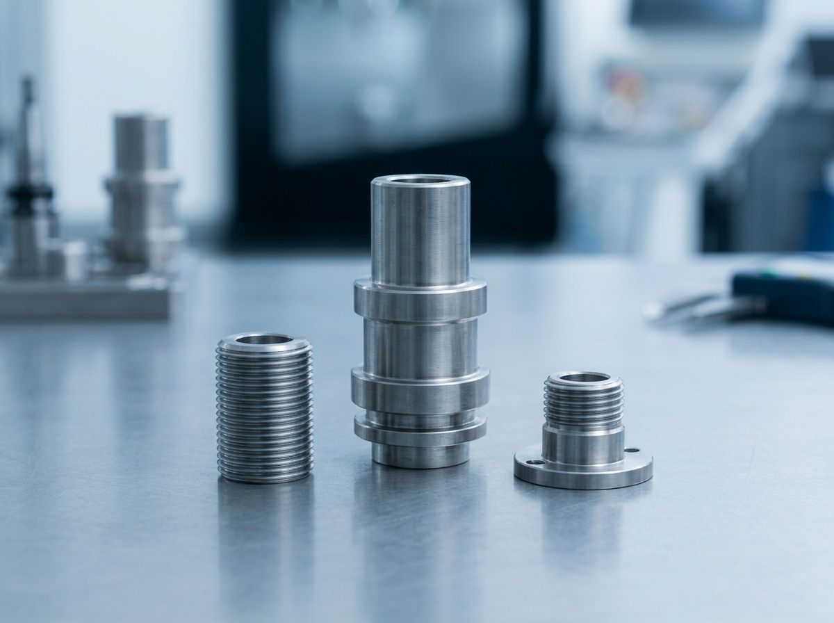
Representative visualization of turned shafts and threaded metal components
Representative manufacturing visual.
02

CNC Turning

Rotational components, threaded parts, bushings and repeat replacement parts

Typical features

  • Shafts and sleeves
  • Internal and external threads
  • Flanges and stepped diameters
  • Rotational features
  • Runout-related requirements

Materials considered

Metals and engineering plastics, subject to grade, condition and geometry review

Technical review focus

Diameter-to-length relationship, workholding, runout, thread definition and secondary operations

What to provide

Drawing with diameters, lengths, thread standards, datum references and inspection requirements

PROCESS ROUTE / PROJECT SPECIFIC
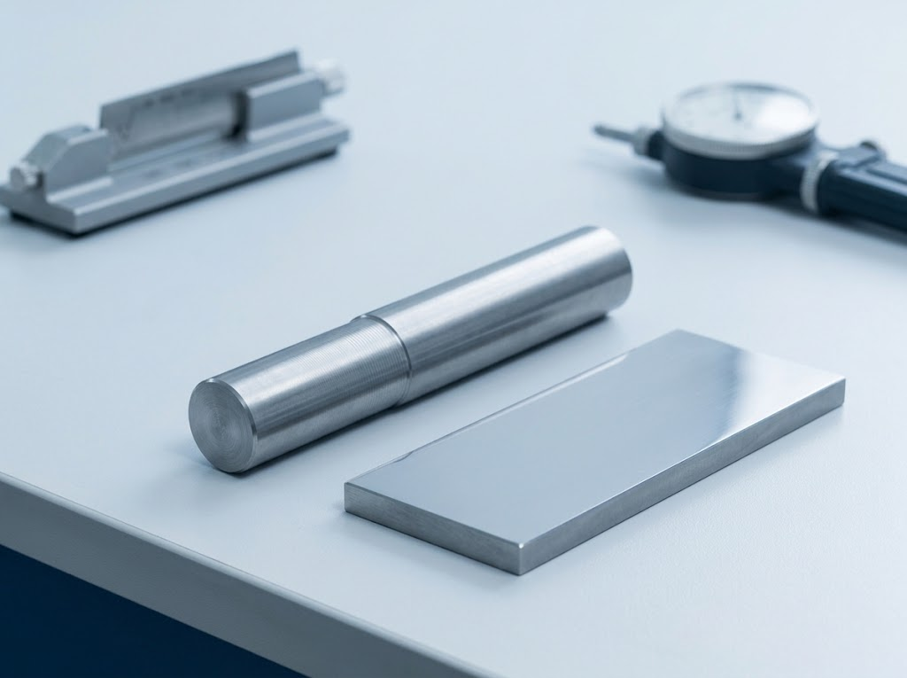
Representative visualization of cylindrical and flat precision workpieces
Representative manufacturing visual.
03

Precision Grinding

Components requiring controlled flatness, cylindrical geometry, dimensional accuracy, or surface finish.

Typical features

  • Flat precision surfaces
  • Cylindrical precision features
  • Geometry and finish requirements
  • Features requiring project-specific inspection

Materials considered

Material type, hardness and incoming condition must be reviewed for each project

Technical review focus

Stock allowance, heat-treatment state, geometry, finish callouts and verification method

What to provide

Drawing, material condition, pre-grind condition, critical features and inspection expectations

PROCESS ROUTE / PROJECT SPECIFIC
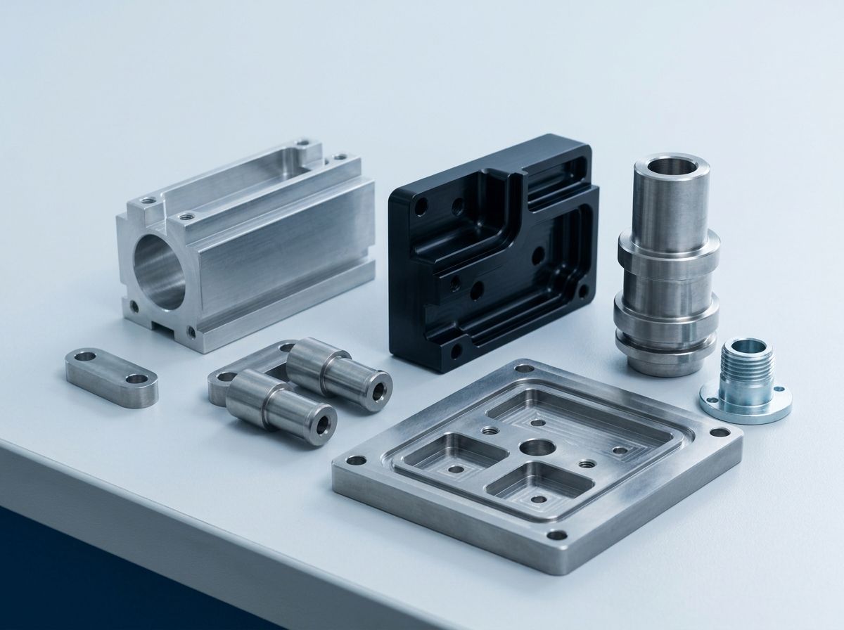
Representative visualization of metal components with varied surface finishes
Representative manufacturing visual.
04

Coordinated Secondary Processes

Completed components requiring one or more coordinated operations after primary machining.

Processes considered

  • Anodizing
  • Passivation
  • Plating
  • Black oxide
  • Heat treatment
  • Powder coating
  • Deburring
  • Assembly

Materials considered

Compatibility is reviewed between base material, condition, finish and functional requirements

Technical review focus

Specification, masking, cosmetic criteria, dimensional impact, documentation and route compatibility

What to provide

Applicable process standard, finish callout, color or appearance criteria, masking and documentation needs

PROCESS ROUTE / PROJECT SPECIFIC

Availability and process routes are confirmed project by project. Resource selection follows drawing and requirement review.

EQUIPMENT + CAPACITY / 03

Machining Capacity for Complex, Multi-Side Parts

Our horizontal and multi-axis machining resources support precision components that require multiple machined faces, stable datum control and fewer re-clamping operations. Equipment is selected project by project according to part size, material, tolerance, geometry and production volume.
  • 01Horizontal machining for multi-face components
  • 02Reduced re-clamping for improved datum consistency
  • 03Small-to-medium housings, blocks, fixtures and mechanical components
  • 04First-article, low-volume and repeat-batch production
  • 05Project-by-project review of drawings, models or physical samples
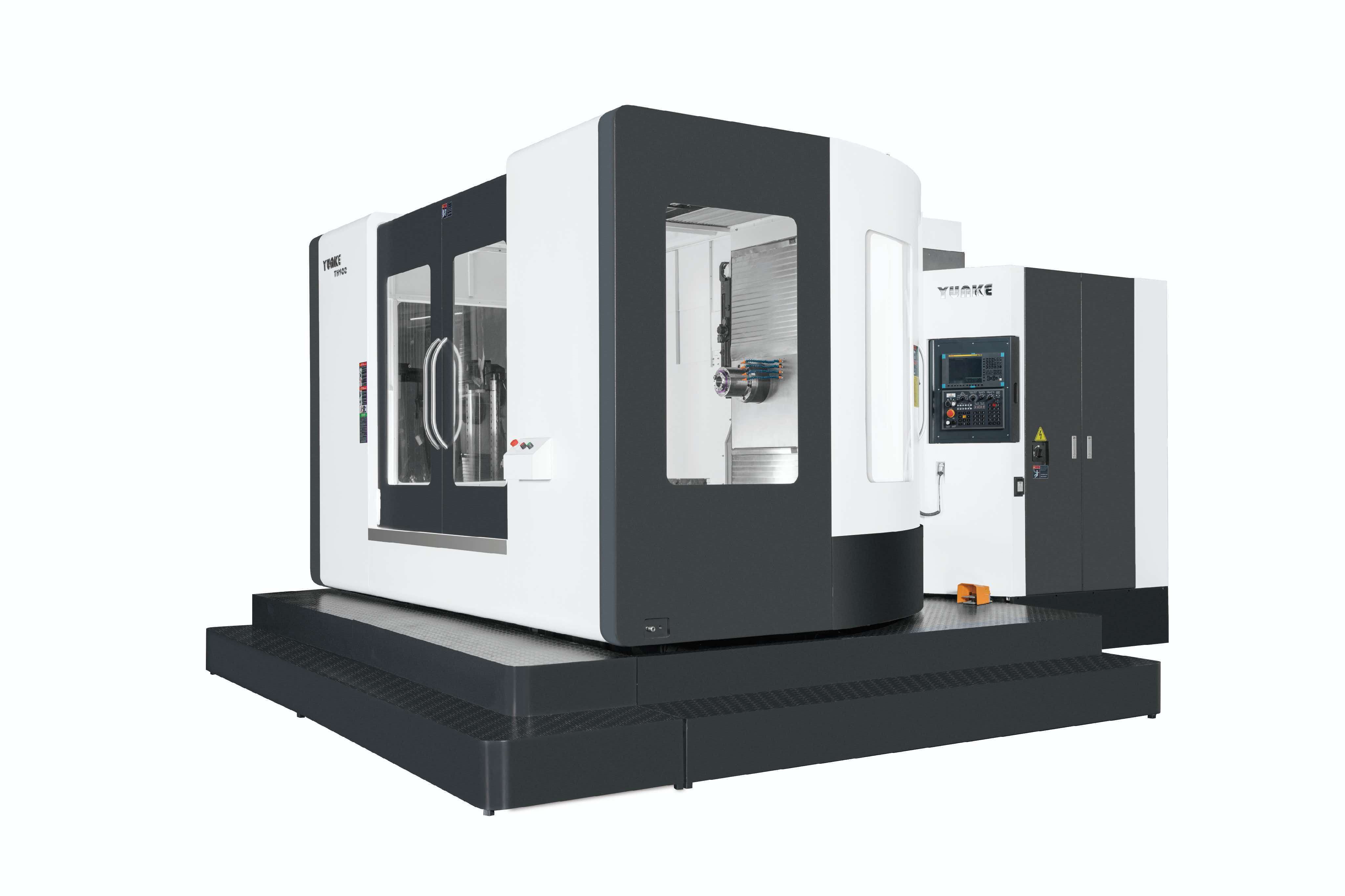
TH63S horizontal machining center with double exchange worktable

TH63S Horizontal Machining Center

Suited to multi-face machining and repeat production where loading and machining efficiency are important.
X / Y / Z travel
1050 × 750 × 900 mm
Worktable
700 × 630 mm
Spindle taper
BT50
Spindle speed
6000 rpm
Worktable format
Double exchange
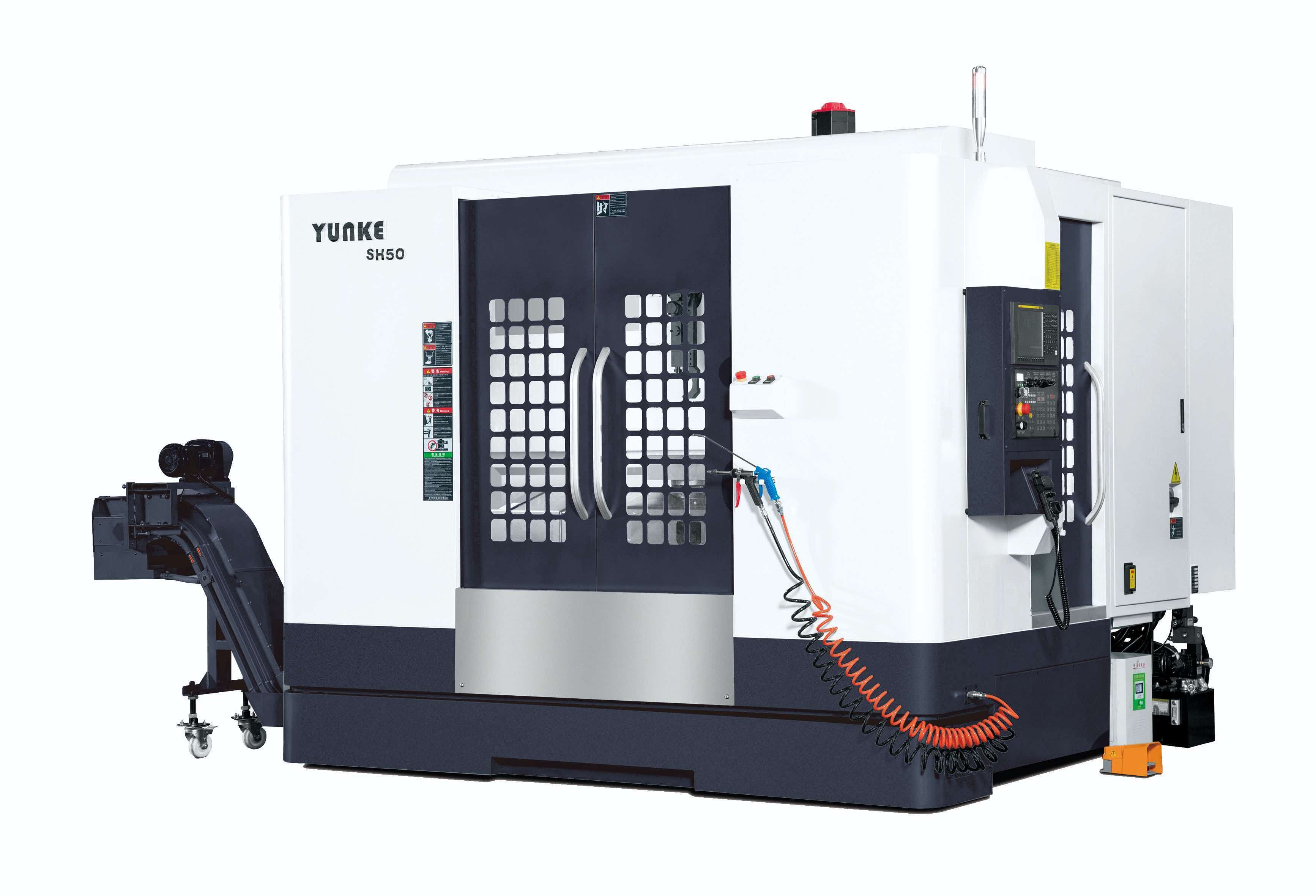
SH50 compact horizontal machining center

SH50 Compact Horizontal Machining Center

Suitable for small and medium-sized precision parts, housings, fixtures and components requiring machining on multiple faces.
X / Y / Z travel
800 × 600 × 600 mm
Worktable
600 × 500 mm
Spindle taper
BT40
Spindle speed
8000 rpm
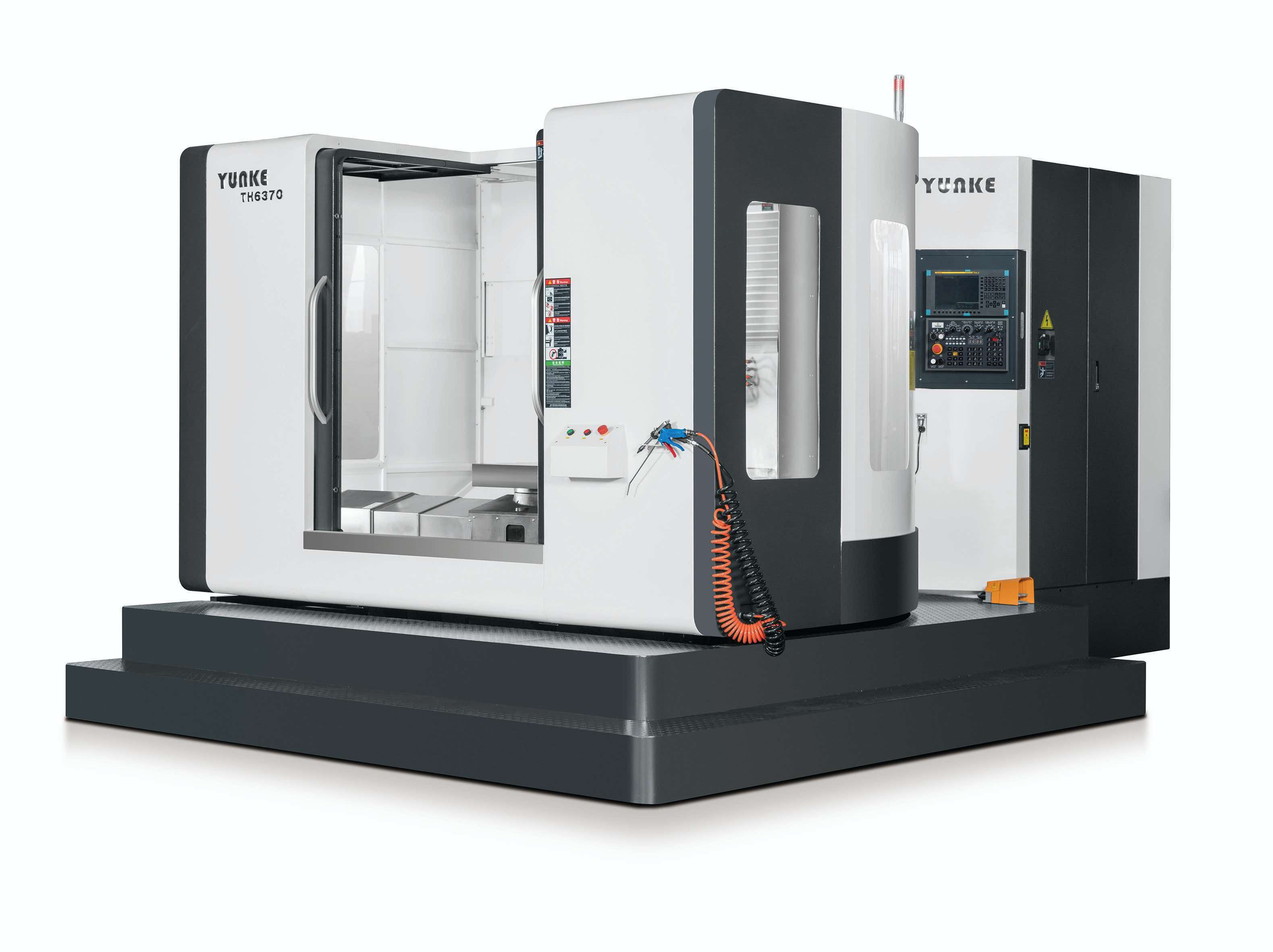
TH6370 horizontal machining center

TH6370 Horizontal Machining Center

Provides a larger working envelope and rigid horizontal-machining configuration for housings, structural components and demanding multi-side work.
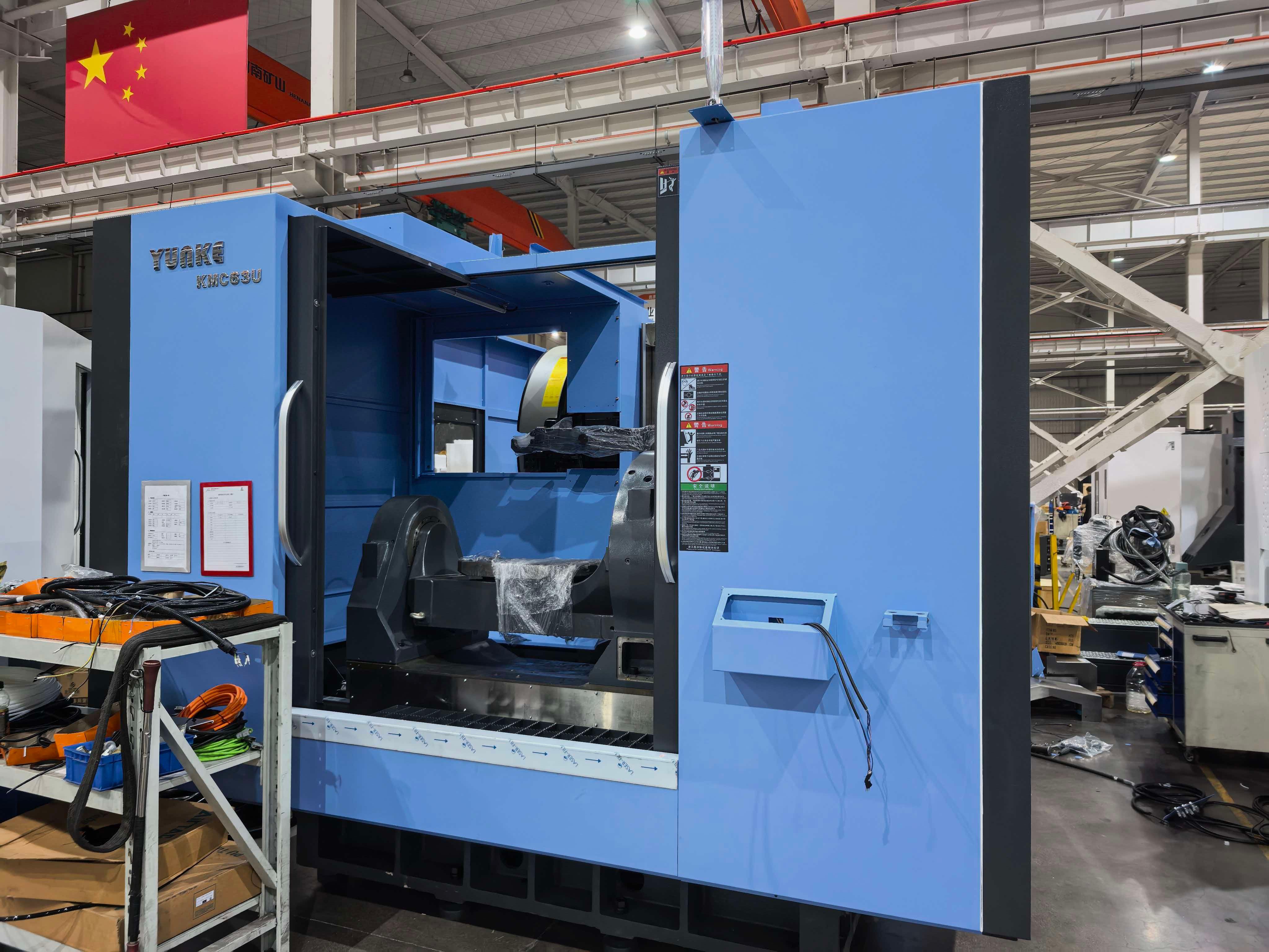
X / Y / Z travel
1050 × 750 (920 listed variant) × 900 mm
Worktable
700 × 630 mm
Spindle taper
BT50
Spindle speed
6000 rpm
General view of machining equipment in a production environment
Production environment visual

PRODUCTION ENVIRONMENT

Machining resources in a production environment

This image is shown for general production-environment context only. Equipment selection and manufacturing routes are confirmed against the drawing, material, tolerance and inspection requirements.

PROJECT REVIEW

Not sure which machining process fits your part?

Send the drawing, 3D model, sample photos or key dimensions. We will review the machining route, equipment fit and inspection requirements before quotation.

Request a Quote

MATERIALS + FINISHES / 04

Materials and downstream processes.

Material selection is considered together with geometry, condition, machinability, finishing, dimensional requirements, verification, and supply needs.
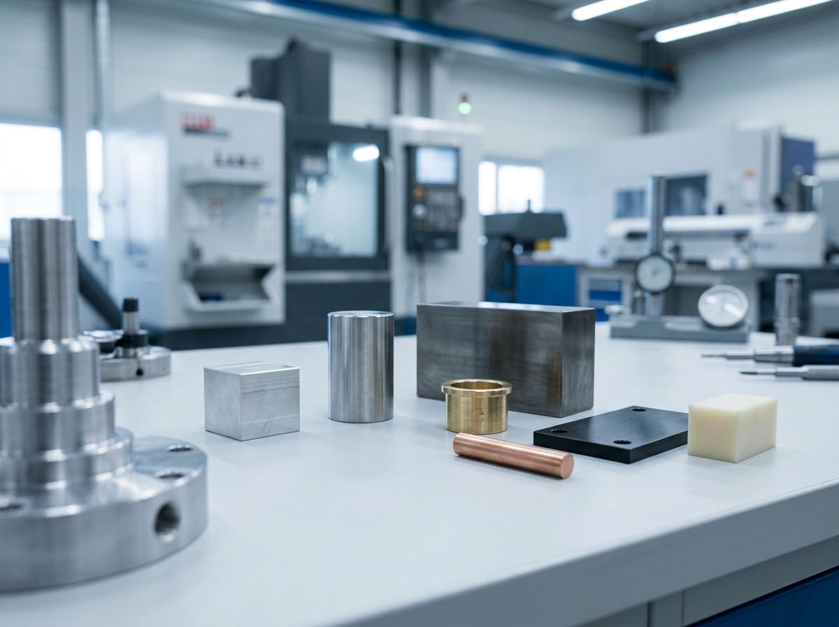
Representative selection of metal and engineering-plastic material forms
Representative manufacturing visual.
Material groupRepresentative examplesProject review focus

Aluminum

Grade confirmed by project

Grade, temper, geometry, finish route and cosmetic requirements

Stainless Steel

Grade confirmed by project

Grade, condition, work-hardening behavior, finish and passivation requirements

Carbon and Alloy Steel

Grade confirmed by project

Grade, hardness, heat-treatment sequence, allowance and corrosion protection

Copper and Brass

Grade confirmed by project

Grade, conductivity or functional requirements, geometry and surface protection

Engineering Plastics

Grade confirmed by project

Material stability, moisture behavior, tolerances, finish and service environment

Other materials upon review

Grade confirmed by project

Availability, machinability, compliance, process route and verification requirements

SECONDARY PROCESSES

Requirements considered as part of the complete route

  • Anodizing
  • Passivation
  • Plating
  • Black oxide
  • Heat treatment
  • Powder coating
  • Deburring
  • Assembly

Subject to drawing review and qualified resource confirmation.

TOLERANCE + INSPECTION / 05

Define the feature before defining the route.

Tolerances down to ±0.005 mm for qualified features and applications. This is not a blanket tolerance for every dimension or part.

01Dimensional tolerance
Material, feature size, geometry, setup, process route and measurement method
02Flatness
Surface area, material condition, stock removal, support strategy and inspection setup
03Position
Datum scheme, feature size, accessibility, setup relationship and verification method
04Concentricity and runout
Datum axis, length-to-diameter relationship, workholding, process sequence and inspection
05Surface finish
Material, process, feature access, directionality, functional need and measurement definition
06Threads
Thread standard, class, depth, material, gauge requirement and any post-process dimensional effect

Achievable tolerance depends on material, part size, geometry, manufacturing process, feature definition, and inspection requirements.
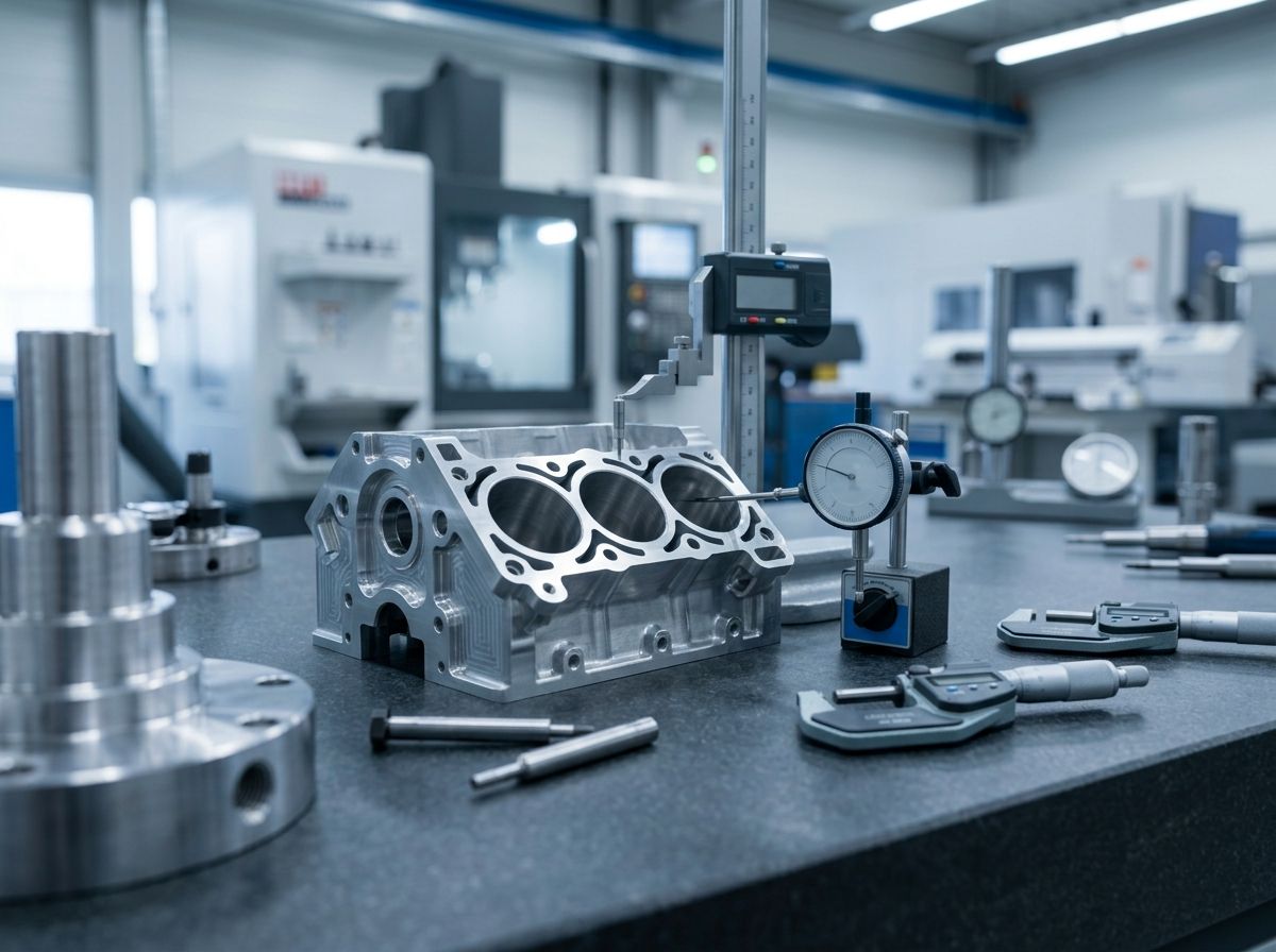
Representative inspection setup with a machined component and measuring instruments
Representative manufacturing visual.

PROJECT FIT / 06

Prepare your project for an efficient manufacturing evaluation.

Clear technical inputs help identify suitable processes, manufacturing resources, inspection needs, and open questions early.
Good fit

  • 2D drawing or 3D model is available
  • Material and quantity are defined
  • Critical dimensions or functional requirements are identified
  • Prototype, low-volume or repeat requirements
  • Project requirements can be confirmed before production

Needs clarification

  • Concept only, without dimensional information
  • Extreme tolerance applied to every dimension
  • Material or finishing requirement is undefined
  • Inspection standard is unclear
  • Safety-critical requirements without defined standards, validation criteria, or responsibilities
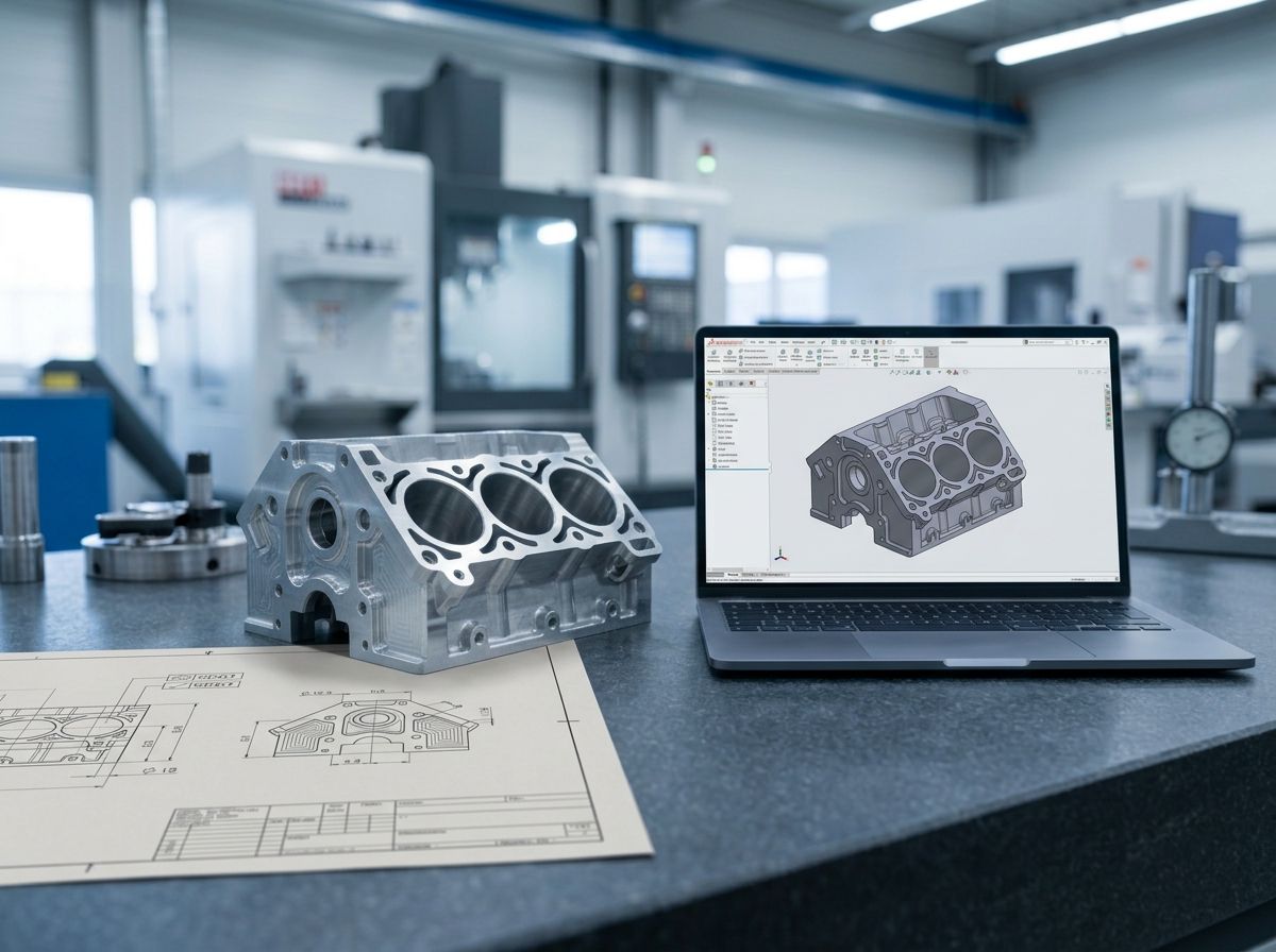
Representative drawing, CAD model, and machined component prepared for project review
Representative manufacturing visual.

RFQ PREPARATION / 07

Information to include with your inquiry.

A complete technical package helps us evaluate the manufacturing route, clarify open requirements, and prepare a more focused response.

  1. 012D drawing
  2. 023D CAD model, if available
  3. 03Material and condition
  4. 04Quantity and repeat demand
  5. 05Critical dimensions
  6. 06Surface-finish requirements
  7. 07Inspection and documentation requirements
  8. 08Delivery destination
  9. 09Target schedule
Submit Your Project

START A REVIEW / 09

Have a Custom Part to Manufacture?

Share your drawing, CAD model, material, quantity, critical features, and quality requirements to begin a focused manufacturing evaluation.

Request a Quote