Dimensional Features
Size, location, orientation, and relationships between controlled features.
QUALITY / REQUIREMENT CONTROL
True Blue connects drawing requirements, manufacturing decisions, inspection expectations, and project documentation throughout the production process.
QUALITY FRAMEWORK / 01
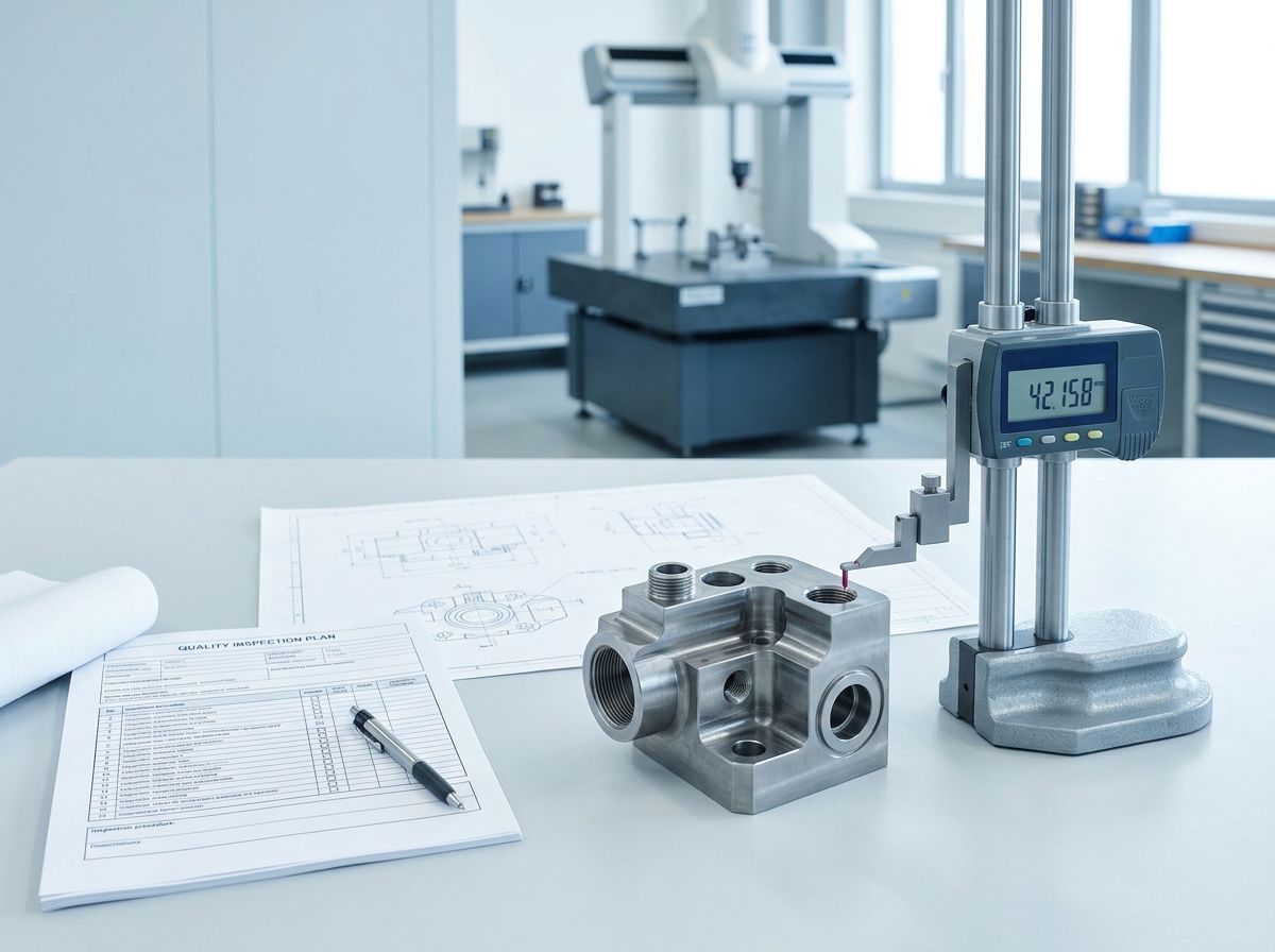
Quality requirements are considered alongside geometry, material, manufacturing route, functional features, quantity, and the customer’s documentation needs.
Identify critical dimensions, datums, tolerances, surface requirements, materials, and applicable customer specifications.
Connect part requirements with an appropriate process route, manufacturing resource, workholding approach, and sequence of operations.
Define which features require verification, the applicable measurement approach, and the records expected for the project.
Coordinate agreed records, revision status, packaging requirements, and release expectations before delivery.
DRAWING + REQUIREMENT REVIEW / 02
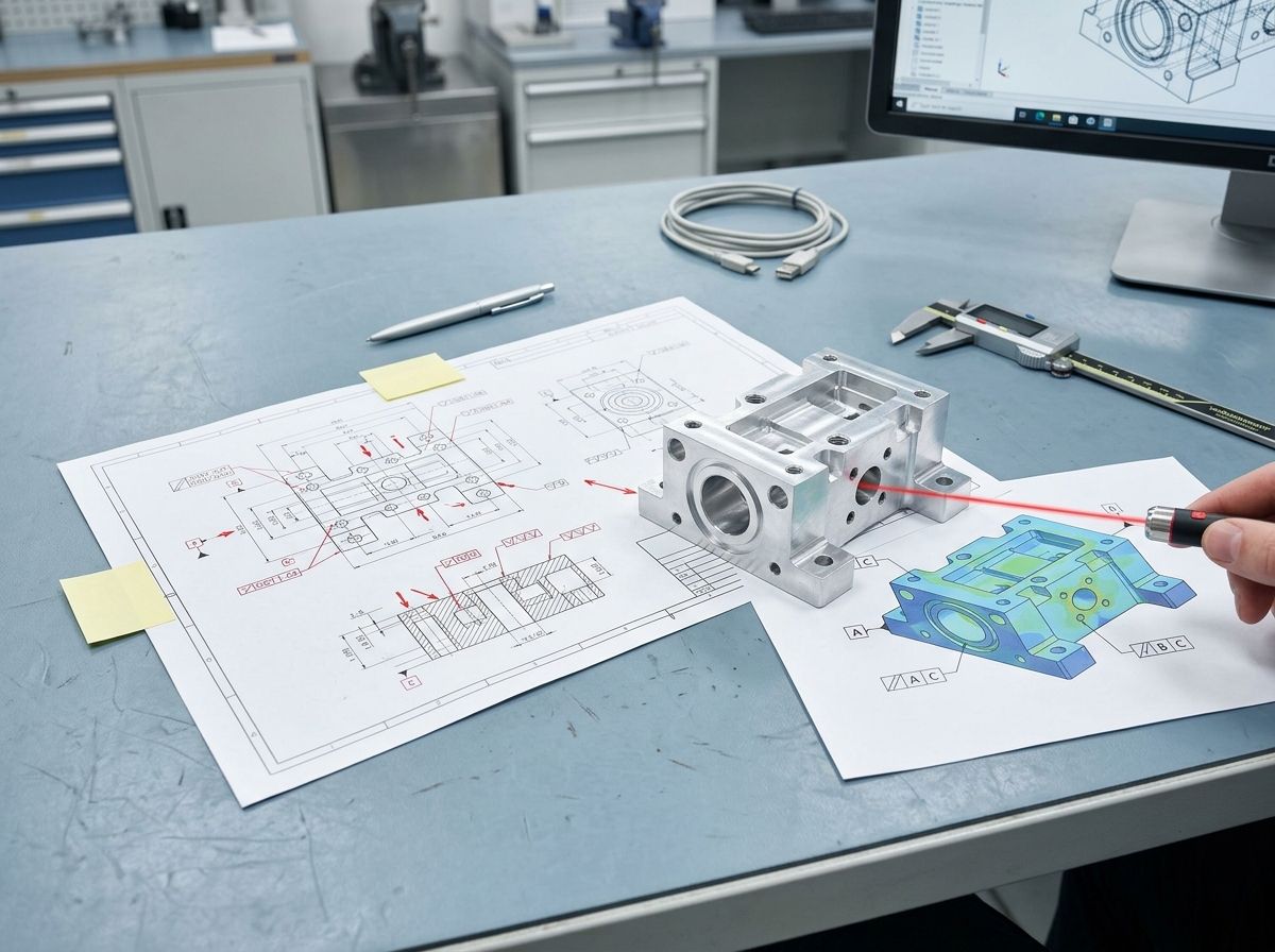
A focused requirement evaluation helps distinguish functional characteristics from general dimensions and identifies questions that should be resolved before manufacture.
Customer-supplied drawings, standards, and acceptance criteria remain the controlling source for each project.
INSPECTION PLANNING / 03
Inspection planning is defined around the characteristics identified for the project—not applied as one standard package to every component.
Size, location, orientation, and relationships between controlled features.
Flatness, position, concentricity, runout, and other drawing-defined controls.
Surface finish, edge condition, cosmetic criteria, and treated surfaces.
Applicable material, heat-treatment, finishing, or process documentation when agreed.
Inspection scope, sampling expectations, report format, and retention needs defined by project.
Agreed verification, documentation, packaging, identification, and delivery requirements.
DOCUMENTATION OPTIONS / 04
Documentation is coordinated according to the drawing, application, customer requirements, and agreed manufacturing route.
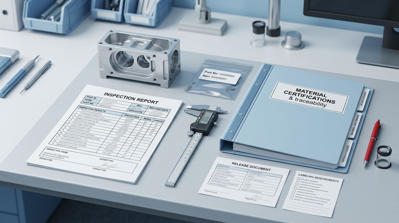
Documentation availability and format are confirmed before production. Not every record applies to every project.
NONCONFORMANCE COORDINATION / 05
When a result does not align with the agreed requirement, the response should remain connected to the drawing, functional impact, verification evidence, and customer direction.
Record the affected feature, requirement, quantity, and available evidence.
Separate affected material and prevent unintended release while the issue is evaluated.
Review the deviation against drawing requirements, function, manufacturing history, and customer responsibilities.
Coordinate the agreed disposition, corrective action, remake, rework, or customer decision as applicable.
No deviation from an agreed requirement is treated as accepted without appropriate authorization.
TOLERANCE RESPONSIBILITY / 06
Tolerances down to ±0.005 mm for qualified features and applications.
Achievable tolerance depends on material, part size, geometry, manufacturing process, feature definition, workholding, and inspection requirements. The applicable capability must be evaluated against the individual drawing.
Identify exactly where the tolerance applies and how it relates to function.
Consider material condition, process sequence, access, stability, and finishing effects.
Confirm datum strategy, measurement access, equipment suitability, and reporting expectations.
CUSTOMER INPUTS / 07
Share what is already defined. Open technical and quality questions can then be identified before production.
QUALITY REQUIREMENTS / PROJECT SPECIFIC
Share your drawing, critical features, material, quantity, inspection requirements, and documentation expectations to begin a focused project evaluation.